


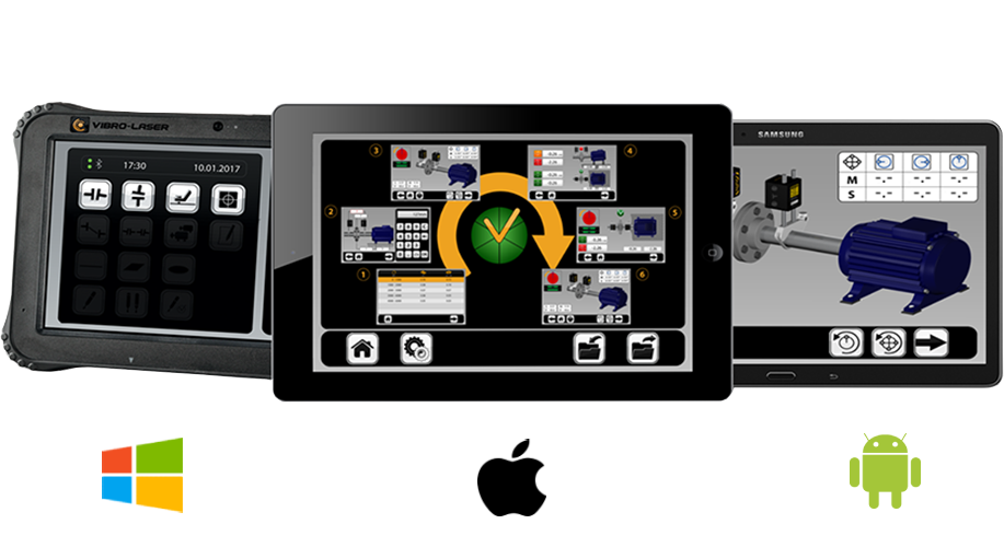
ROKADE RotoTechniks is pleased to present the latest innovation in wireless portable laser shaft alignment technology, the VLSAT. VLSAT is available for Android® tablets, iOS® for iPad®. Microsoft Windows®. It is the only 3 Operating system Laser Shaft Alignment System. You have a choice with VIBRO-LASER. Select your display tablet option from those we offer, or bring your own device that meets or exceeds our minimum requirements.
VLSAT is ergonomically designed for the most rugged environments. This product is an absolutely innovative, step-by-step, responsive interface with 3D-animations and wide touch screen, which simplifies the alignment process and reduces the time it takes to complete each alignment.
The unbeatable functionality and the undeniable performance capabilities of VLSAT systems allow you to complete precise alignments for your rotating assets every time. Rugged, Repeatable, and Relentlessly Reliable your VIBRO-LASER VLSAT system will prove to be an invaluable asset in your reliability toolkit.
VLSAT™ Laser Shaft Alignment System is the world's fastest and easiest to use laser shaft alignment system.
Improve asset availability & uptime through precision alignment.
Wireless Bluetooth® Communication for Safety.
Reduce unnecessary costs associated with unplanned failures & premature wear.
Reduce your energy Consumption.
5-Steps-Simple™Â alignment Process.
More efficient, and faster than dial indicators.

Operating time 20 Hours
Measurement distance Up to 10m

Degree of protection IP65

Detector type Digital CCD detector 30mm

Operating temperature: 14o F to 140o F (-10o C to +60o C)

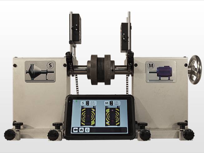
HORIZONTAL ALIGNMENT

CLOCK METHOD
This alignment method requires collecting a measurement points at any 3 of the 4 pre-defined clock positions. (3-6-9-12 O' clock).

POINT METHOD
This alignment method allows you to begin collecting measurement points at any angle of shaft rotation and automatically collects a measurement anytime you stop rotation. Minimum of 40 degrees of rotation is required.

CUT ANGLE
This alignment method is best used when 180 degrees of shaft rotation is not possible. The minimum required shaft rotation is 40 degrees. The more rotation, the better and more precise the alignment.

VERTICAL ALIGNMENT
Vertical shafts alignment is carried out by moving the machine flange/coupling until the axes are coaxial enough to stay in the assigned limits.
Note! Coupled and Uncoupled Shaft.

SOFT FOOT
Before any alignment soft foot should be addressed.

MACHINE TRAIN
This alignment method is for aligning multiple components across several couplings. Coming soon

THERMAL GROWTH CORRECTION
Easily and accurately compensate for thermal growth using the VLSAT thermal growth correction module.
UTILITIES

ZONE EXPANSION
Unique technology that reduces the efffects of high vibration and competing light sources on precision alignment.

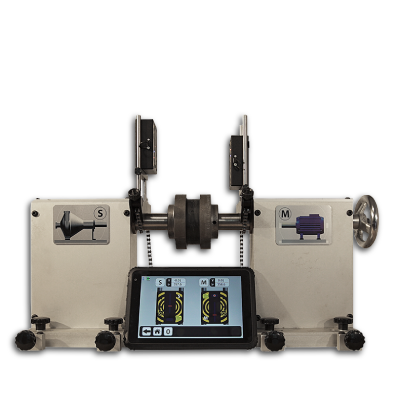
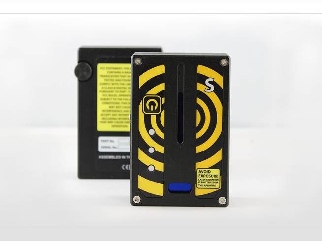
SENSOR UNIT READINGS
The display shows data received directly from thesensor units (position of the laser beam on the sensor and inclinometer).

MULTIPLE SETS OF FEET (coming soon)
Allows the user to align machines with more than two sets of feet.

SMART MEASUREMENT VALUE FILTER
statistically analyzesmeasurement values and normalizes data collected utilizing a 95% confidence interval to insure the data points used to calculate alignment corrections are representative of the entire dataset. Best used in high vibration areas. (coming soon).

SwitchIT™ FUNCTION (coming soon)
Before any alignment soft foot should be addressed.

CONTINUE ALIGNMENT
Start a new alignment, redo a previously completed alignment, or save at any step in the alignment process and go back to finish anytime.

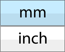
Choose your system of measurement.
Touch the Icon “Sensor units search”. After initial use the sensor units the software will automatically connect to the applicable heads.

SAVING DATA AND REPORT CREATION

SAVING DATA
Saves your alignment job and all respective measurements, photos, and details to the database for easy access later.

REPORT CREATION
Generates a PDF report.

ADD PHOTO
Allows the user to take a photo with their devices internal camera of the machine being aligned for reporting purposes.

SEND THE REPORTS
When configured allows the user to easily send reports via their email client / service.

SAVE TO USB
Allows the user to export alignment job data to USB for use with other VIBRO-LASER systems.

ADD NOTES
Allows the user to manually enter notes related to the alignment job or about the machine being aligned. This tool is great for general observations.
Tecnical Specification
| Material | Anodized aluminium |
|---|---|
| Dimensions | 90 x 60 x 32 mm |
| Laser radiation | Diode laser with laser wavelength 635 nm, class II |
| Laser power | < 1 mW |
| Measurement distance | Up to 10m |
| Detector length | 30 mm |
| Detector type | Digital CCD detector |
| Measurement accuracy | 0.3% ± 7 m |
| Inclinometer | 0.1 |
| Degree of protection | IP65 |
| Operating time | up to 20 Hours |
| Bluetooth | 4.0 |
| Operating temperature | 14o F to 140o F (-10o C to +60o C) |
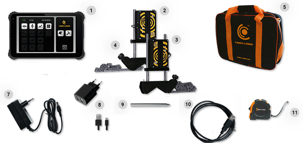
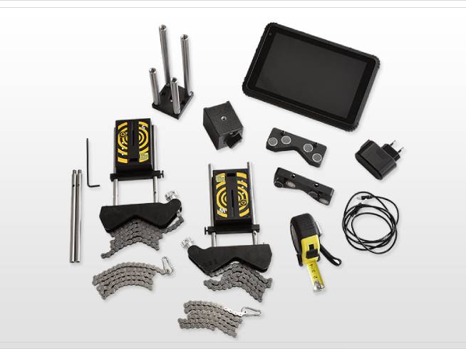
Complete Set
1. Display unit (1pcs IF INCLUDED).
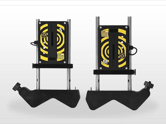
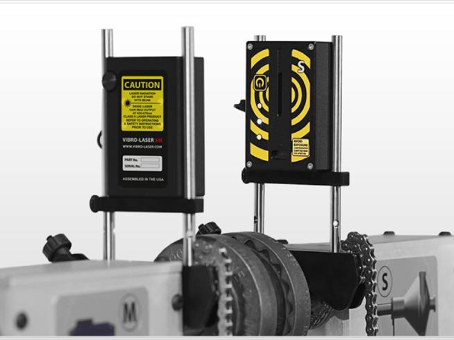
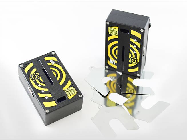
2. Sensor unit S (1pcs).
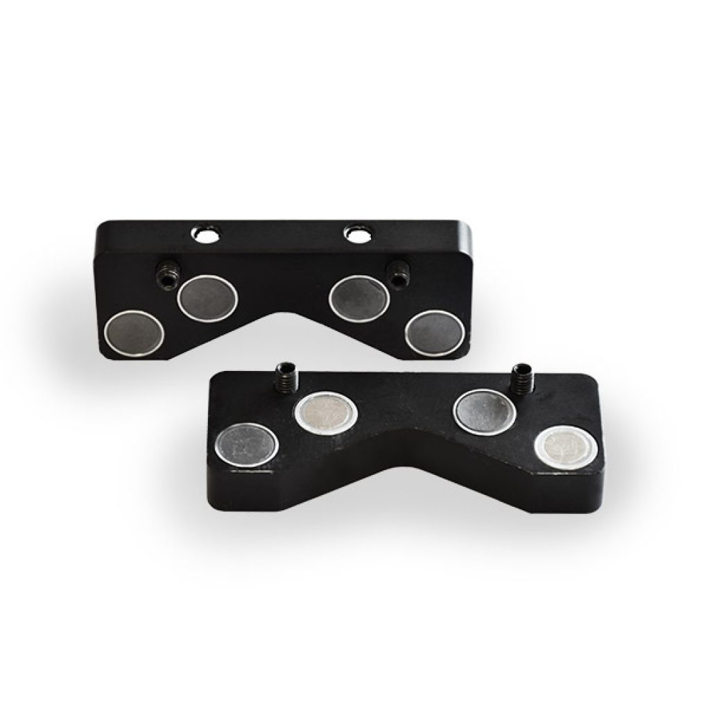
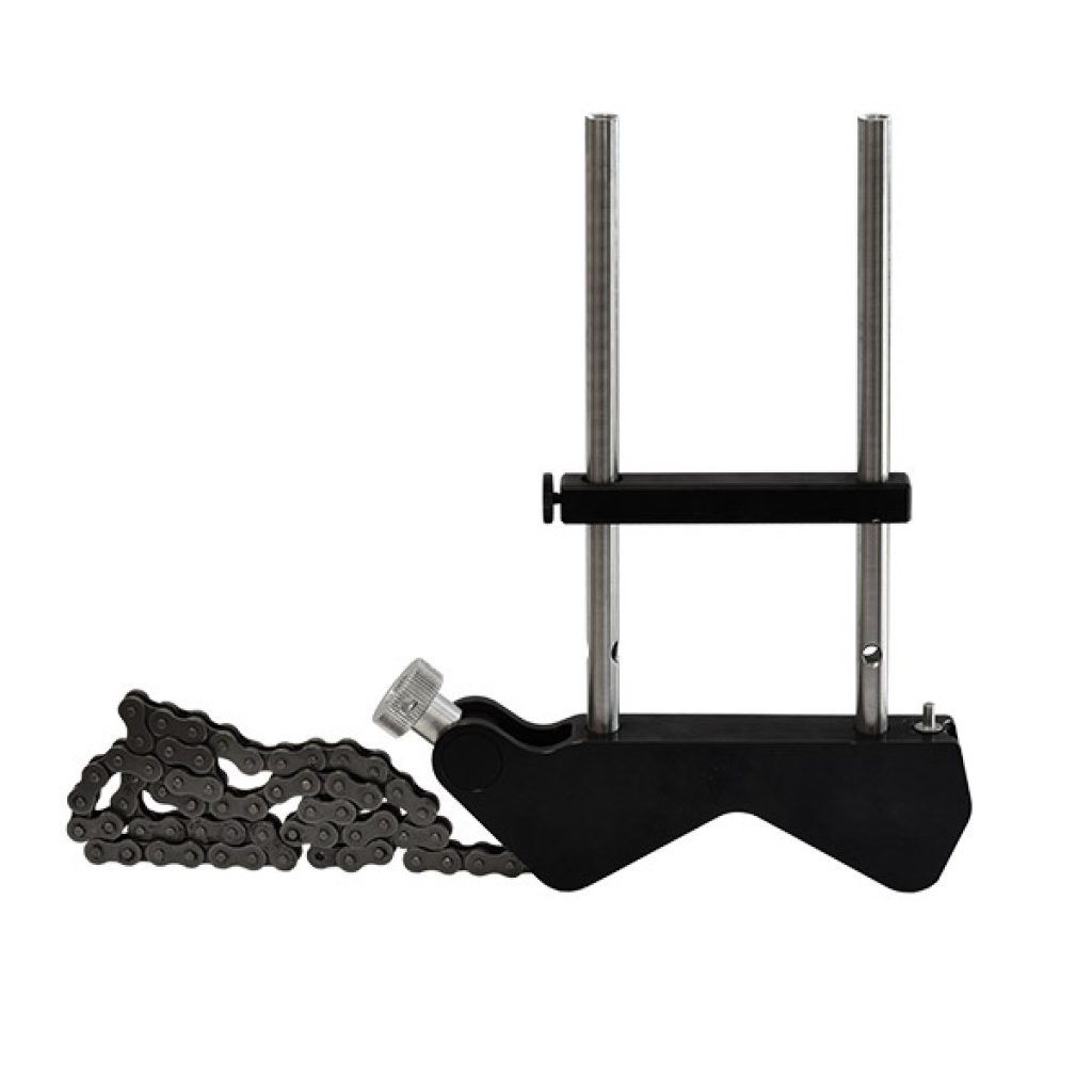
3. Sensor unit M (1pcs);4. Complete v-bracket (2pcs).
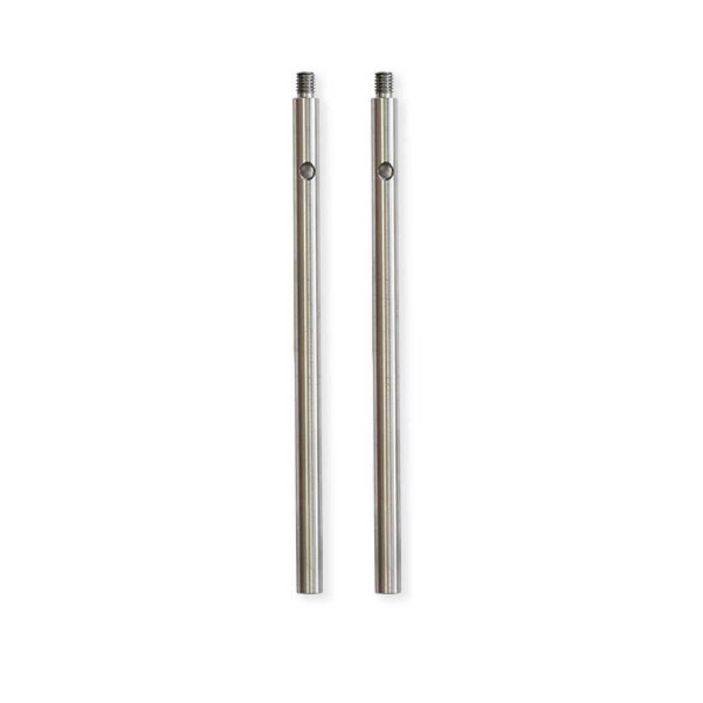
4. Complete v-bracket (2pcs).
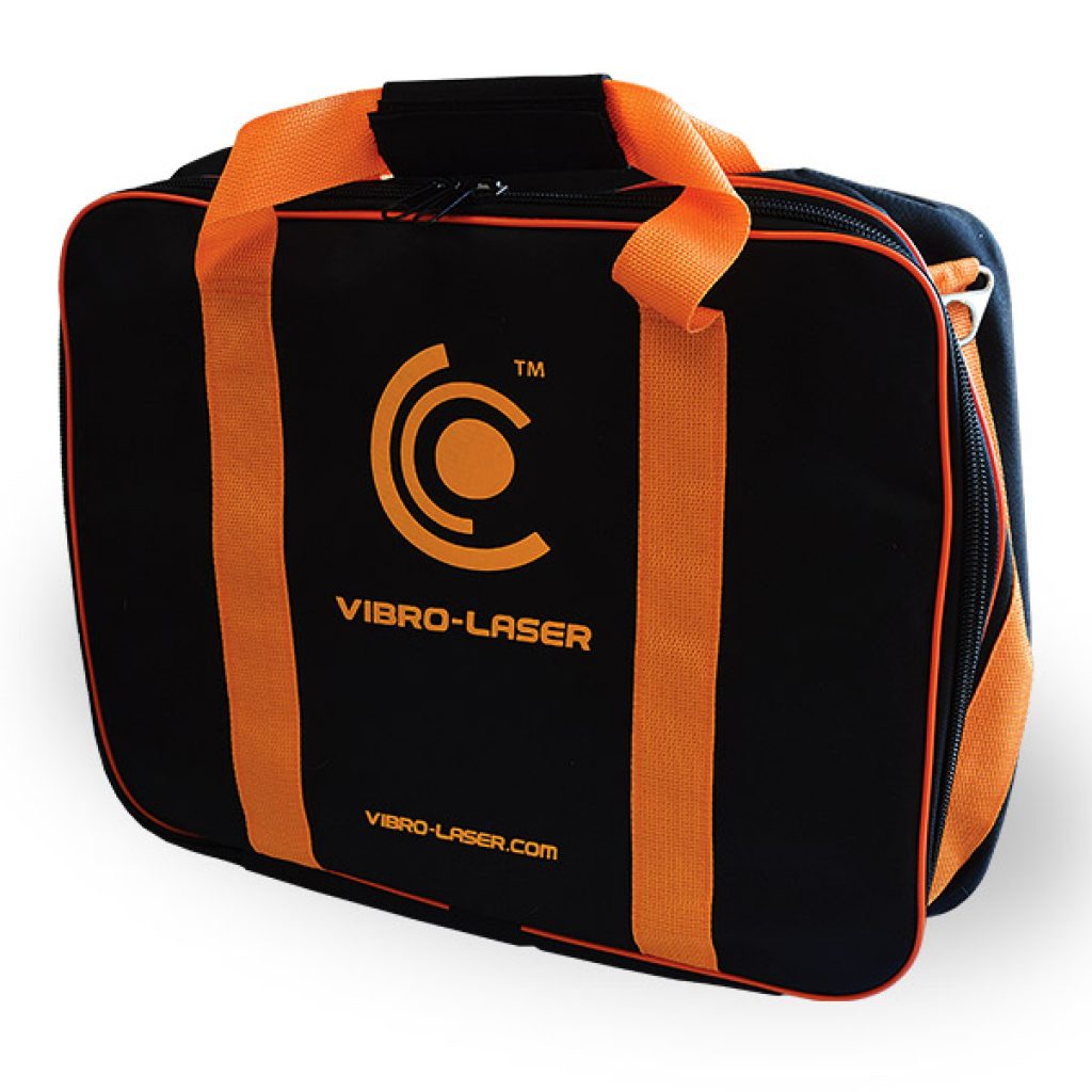
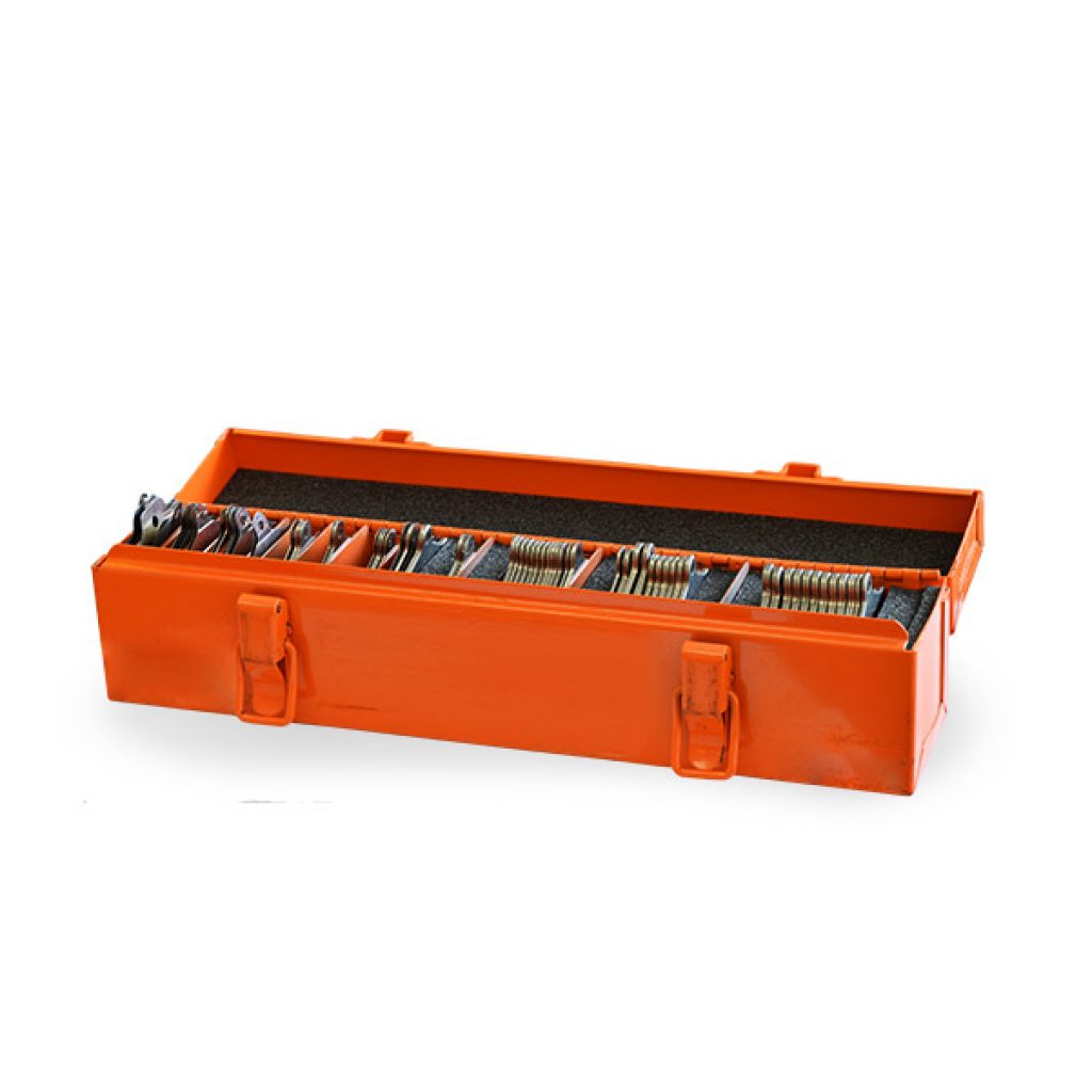
5. Carring bag (1pcs).
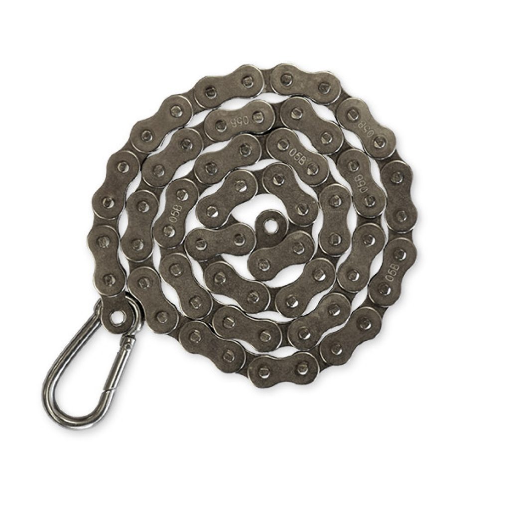
6. Chain with lock (2pcs).
7. Display unit adapter (1pcs).
8. Sensor units adapter (1pcs).
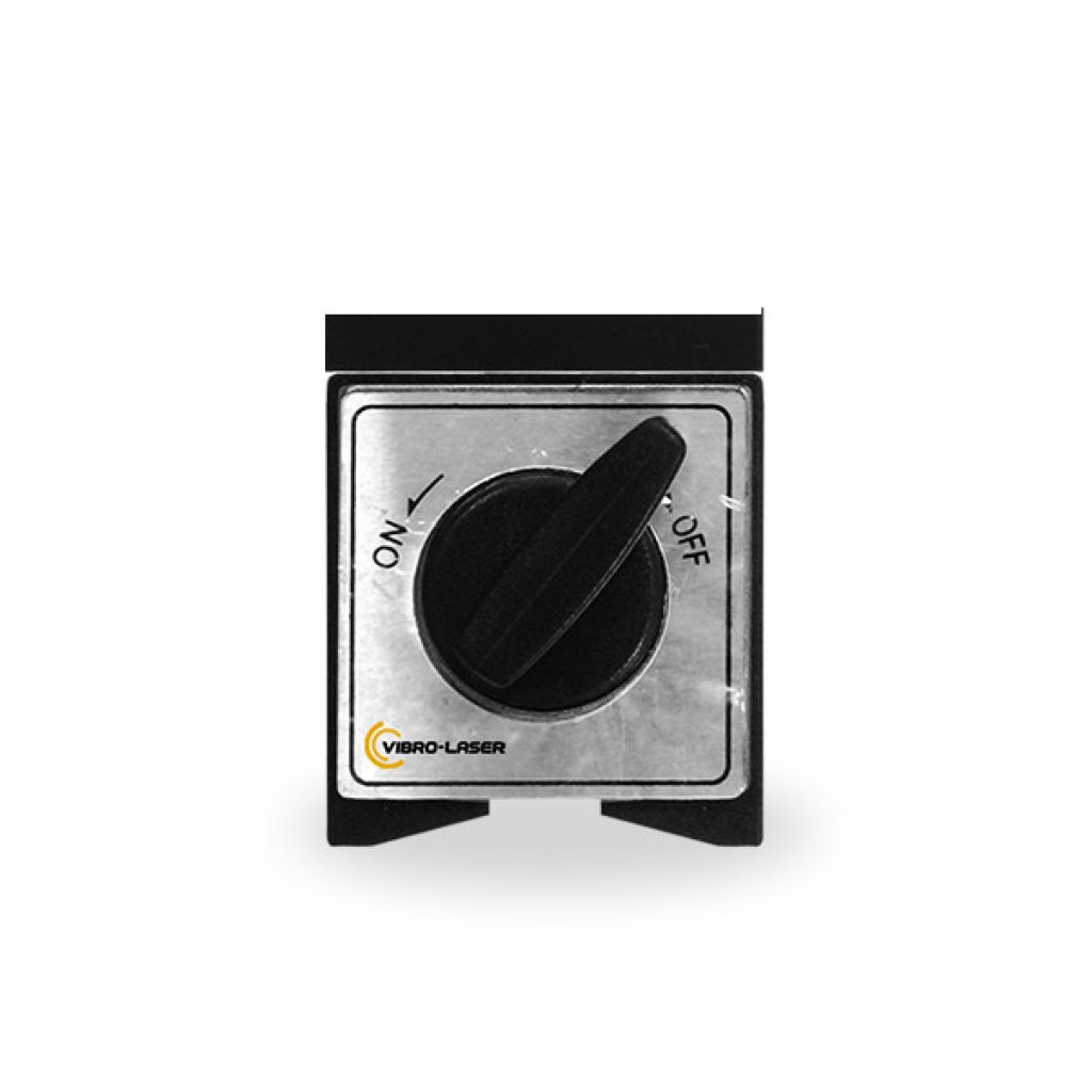
9. Turn key (1pcs).
10. USB cable (2pcs).
11. Tape measure (1pcs).
Accessories
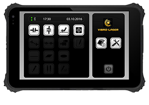
TABLET- 8inch
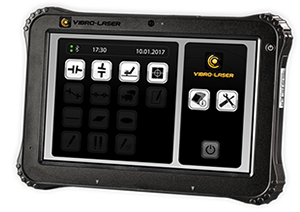
TABLET- 10inch
VLSAT Accessories
VLSAT the Next Generation of Laser Shaft Alignment
VIBRO-LASER VLSAT New Features 2-2018
VLSAT SETUP and LICENSING

Thane
Corporate Office

Delhi
Factory & Office

Chennai
Branch Office
Copyright ©2022 Rokade RotoTechniks All Rights Reserved.


