- Ranipet
- Sivakasi
- Karur
- Udhagamandalam
- Hosur
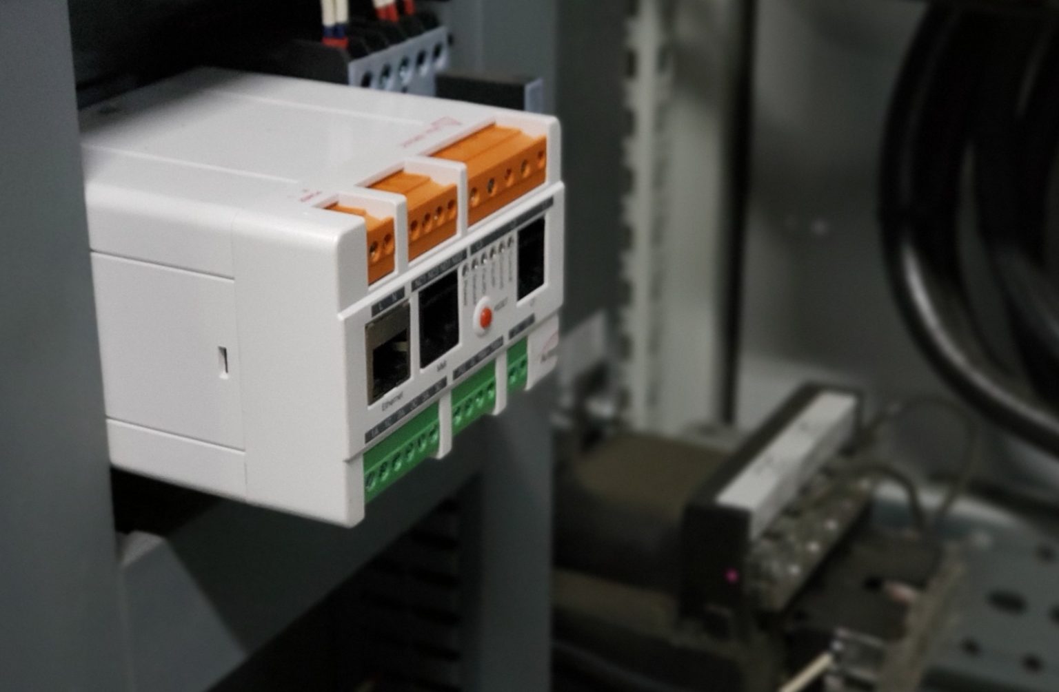
E-PCM monitors the condition of generators and their prime movers, effectively using the generator itself as a sophisticated transducer. It uses advanced NASA-developed technology to provide automated set-up and fault diagnosis with minimal user intervention. It is simpler to use and more cost-effective than conventional systems. e-PCM is applicable to a very wide range of equipment, including turbo-alternators, diesel generators, and wind turbines, and is particularly valuable for equipment in inaccessible or hazardous environments.
Wind Turbine and Generator Condition Monitoring
Easy installation from a single point with alternator current and voltage information without sensors.
Maintenance planing information including diagnostic and time to failure
Easy to use and no need for interpretation by a highly trained person
Detects and diagnoses exsisting and develoing faults
Verifies effectiveness of the maintenance action taken
Unlimited trend recording
PSD -Power Spectral Density
Easy installation from a single point with alternator current and voltage information without sensors.


Simple to Install
Installing e-PCM is a simple matter of connecting it to the three supply phases of the generator using simple and inexpensive transducers and mounting it in any convenient panel. It is usually located at the generator control cabinet, requiring very short cable runs and avoiding the need to install equipment in remote or hazardous areas. When first switched on, e-PCM carries out an automatic self-learning process during which the normal operating condition of the equipment is established. Advanced analysis techniques ensure that this training takes account of variables like speed and load, and that existing faults do not result in training errors.
Continuous Monitoring of Your Generator
e-PCM constantly takes measurements and compares them with its reference condition, in order to assess the severity and type of any developing fault. It is able to recognise abnormalities in a wide range of operating states, and is even able to extend its self-learning process when it recognises that it has moved beyond its original learning limits. This allows e-PCM to achieve very sensitive detection of faults without false alarms.


Reliable, Automated Fault Diagnosis
When e-PCM detects a fault, it presents the results of its sophisticated analysis to the user in a simple, compelling traffic light display. This provides local staff with an immediate indication that a problem is developing. Detailed diagnostic information is provided by means of its standard networking facilities, and covers a very wide range of mechanical and electrical problems including imbalance, misalignment, bearing damage, gearbox faults, isolation, and many others. A relay output is also provided so that specific alarm conditions can be annunciated by visual or audible warnings, or communicated to a control system.
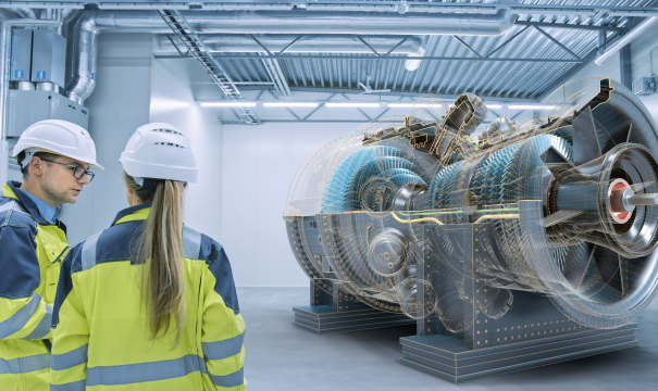
e-PCM creates a digital twin of generators and their prime movers such as wind turbines. The digital twin is built up during self-learning phase of operation. During this phase the three voltages and three currents are continuously measured and processed using system identification algorithms which determine the model parameters under a full range of operating states.
When a fault starts to develop in either the generator or the prime mover, this has an effect on the current waveform, making the real system behave differently from the model system. This allows e-PCM to use the generator as a sensor that can detect faults in both the generator and the prime mover. e-PCM continuously compares model parameters with those held in the reference model.
Turbine blades
Misalignment
Mechanical Damages
Gear box
Wear, crack in gears
Looseness
Eccentricity
Generator Bearings
Ring and ball damage
Crack
Corrosion
Lubrication problems
Alternator
Unbalance
Axial misalignment
Cracks in the rotor bars
Short circuit and insulation problems in wound rotors
Rotor eccentricity
Short circuit, insulation weakening and looseness in stator windings
Heating problems at motor terminal connection points
Current unbalance and voltage unbalance
Cable damages and connection faults
Mechanical Faults
Loose Foundation
Loose Components
Unbalance
Misalignment
Coupling
Bearing
Transmission Element
Rotor faults
Electrical Faults
Loose Windings
Stator
Short Circuit
Internal Electrical
External Electrical
Energy production information
Instant active power (kW)
Instantaneous reactive power (kVAr)
Total active power (kWh)
Total reactive power (kVArh)
Working hours information
Total working hours
Last working hour
Previous working hour
Energy statistics on equipment
Active power demand graph
Day and month summary
Harmonic Analysis
THD
Odd harmonics – 3,5,7,9,11,13
Frequency
Current and voltage imbalances
Power factor
3 phase current and voltage RMS values
TAMIL NADU
ANDHRA PRADESH
KARNATAKA
KERALA
TELANGANA
MAHARASHTRA
GOA
GUJARAT
UTTAR PRADESH
DELHI
RAJASTHAN
PUNJAB
HIMACHAL PRADESH
HARYANA
UTTARAKHAND
WEST BENGAL
ODISHA
JHARKHAND
BIHAR
MADHYA PRADESH
CHHATTISGARH